Printed circuit board edge connectors are one of the most important aspects of any PCB Layout and design service UK. They are responsible for connecting the different parts of the circuit board together and making sure that the electrical signals can flow between them properly. There are many different types of edge connectors, but the most common one is the pin header.
PCB Edge Connectors: Types and Applications
PCB edge connectors are used to connect a printed circuit board manufacturer uk (PCB) to another PCB or electronic device. There are two main types of PCB edge connectors: D-sub connectors and F-connectors. D-sub connectors are typically used for connecting PCBs to computers, while F-connectors are used for connecting PCBs to other electronic devices. PCB edge connectors can be either through-hole or surface-mount. Through-hole edge connectors are typically used for connecting thicker PCBs, while surface-mount edge connectors are used for connecting thinner PCBs.
What are PCB Edge Connectors?
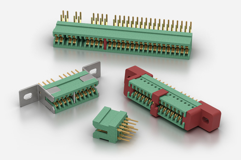
A printed circuit board edge connector is a device used to connect a printed circuit board (PCB) to another PCB or electronic device. They are commonly used in computers, telecommunications equipment, and other electronic equipment. Edge connectors are designed to be inserted into a slot on the edge of a PCB. The edge connector consists of a row of metal contacts that are inserted into corresponding holes on the PCB. The edge connector is then soldered to the PCB.
Advantages of PCB Edge Connectors
The main advantage of PCB edge connectors is that they offer a very reliable electrical connection between the PCB and any external devices. They are also very easy to use and can be fitted quickly and easily. Another advantage is that they can be used with a wide variety of PCBs and do not require any special tools or equipment.
Disadvantages of PCB Edge Connectors
PCB edge connectors are used to connect electronic components to a printed circuit board (PCB). They are typically used to connect the PCB to another PCB or to a daughter board. Edge connectors can be either through-hole or surface-mount.
PCB edge connectors have a number of disadvantages. They are susceptible to dust and dirt, which can cause electrical shorts. They are also susceptible to mechanical damage, which can cause the connection to break. Additionally, edge connectors can be difficult to solder, and the connection can be easily broken if the PCB is bent or flexed.
How to Solder a PCB Edge Connector
PCB edge connectors are used to connect electronic components to a printed circuit board (PCB). They are typically made of copper and have a plated finish that is designed to resist corrosion. Soldering is a process of joining two metals together by heating them to a melting point and then using a filler material to bond them. In order to solder a PCB edge connector, you will need a soldering iron, a piece of solder, and a flux-cored wire.
1. Begin by heating the soldering iron to its working temperature.
2. Place the flux-cored wire on the joint between the two pieces of metal that you wish to solder.
3. Hold the solder against the joint and touch the tip of the soldering iron to the solder.
4. Allow the solder to flow into the joint and then remove the soldering iron.
5. Allow the joint to cool before handling.
PCB Edge Connector Manufacturers
There are many Printed Circuit Board (PCB) edge connector manufacturers that provide a variety of options for customers. Some of the most popular manufacturers include Molex, JST, and TE Connectivity. These companies offer a wide range of products, from simple two-pin connectors to complex multi-pin connectors. Some of the products offered by these manufacturers include:
-Molex offers a wide variety of edge connectors, including the popular Mini Fit Jr. series. These connectors are available in a variety of pin counts, from 2 to 24.
-JST offers a wide range of edge connectors, including the popular XH series. These connectors are available in a variety of pin counts, from 2 to 36.
-TE Connectivity offers a wide range of edge connectors, including the popular AMP-Latch series. These connectors are available in a variety of pin counts, from 2 to 24.
PCB Edge Connector Suppliers
There are many PCB edge connector suppliers in the market that provide edge connectors for printed circuit boards. These suppliers offer a wide range of edge connectors that are made from different materials and come in various sizes and shapes. Some of the most popular edge connector suppliers include Samtec, Molex, JST, and TE Connectivity. These suppliers offer a variety of edge connectors that are suitable for different applications.
PCB Edge Connector FAQs
PCB edge connectors are electronic components that are used to connect two printed circuit boards (PCBs) together. They come in a variety of shapes and sizes, and are typically made of copper or other conductive materials.
There are a few things to keep in mind when choosing PCB edge connectors for your project:
-The number of pins: This will determine how many connections can be made between the two PCBs.
-The pitch: This is the distance between the centers of two adjacent pins.
-The thickness: This is the thickness of the connector, which needs to be compatible with the PCB thickness.
-The material: Copper is the most common material used for edge connectors, but other materials such as aluminum can also be used.
Make sure to check the specifications of the PCB edge connectors to make sure they are compatible with your PCBs.
Related Articles
Edge connectors are used to connect a printed circuit board (PCB) to another PCB or electronic device. They are typically made of metal and have a row of pins or contacts that matingly connect with the other device. Edge connectors are often used in computer hardware, as they provide a reliable and secure connection between two devices.